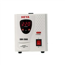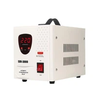



A high voltage regulators is a device designed for high voltage applications that automatically adjusts output voltage, even if input voltage fluctuates or the load changes are stable. Through the advanced circuit and control mechanisms, the output voltage is stable in the specified range, protecting high voltage equipment from voltage fluctuations. Here's a closer look:
I. Core Functions
Voltage Stabilization
When input voltage fluctuates (e.g. due to grid voltage fluctuations) or the load current changes, the voltage regulator automatically adjusts the output voltage to stay within the rated range (usually error ± 1%).
For example, if the input voltage fluctuates between 200V and 240V, the output voltage can be stable at 220V ±1%.
Overvoltage/Undervoltage Protection
Monitor output voltage and automatically cut off power supply or activate protective circuit to prevent equipment damage when voltage exceeds or falls below safety threshold.
For example, when output voltage exceeds 242 V (220V +10%), the regulator triggers an overvoltage protection.
Filtering and Noise Suppression
Suppresses harmonic, noise and transient pulses in the power grid, provides clean and stable voltage, and improves equipment reliability.
Suitable for applications with high power quality requirements (such as medical devices, precision instruments, etc.).
ii. Principles of work
Thevoltage regulator achieve voltage stabilization through the following mechanisms:
Input Voltage Detection
input voltage is continuously monitored and compared with the set reference voltage.
Error Amplification and control
When input voltage changes causing the output voltage to deviate from the set value, the error amplifier amplifies the deviation signal and transmits it to the control circuit.
Adjustment Element Action
Mechanical Adjustment Type: using a servo motor to move brush along the winding of automatic transformer, changing the position of output voltage switch (such as traditional voltage regulator).
Electronic Adjustment Type: Fast adjustment of Switch occupancy duty cycle conduction conduction angle and conduction angle using power semiconductor devices (e.g. IGBT, MOSFET) to control output voltage (e.g., high-frequency switching regulators).
Closed-Loop Feedback Control
The output voltage is fed back to the control unit through the sampling circuit, forming a closed-loop system to ensure the stability of the continuous output voltage stability. III. Main Typess
According to the working principle and structure of HV regulators, HV regulators can be divided into the following categories:
Type Feature Application Scenarios
Automatic transformer regulator adjusts voltage by moving a carbon brush along an automatic transformer tap. Simple in structure but slow in response (milliseconds). Industrial equipment, low-voltage distribution network
Inductive Regulator adopts electromagnetic induction to regulate voltage, and has strong anti-jamming ability, but it is small in size and high in cost. ... large remote factories with unstable power grids.
Magnetic Saturation Regulator takes advantage of the magnetic saturation characteristics magnetic core, with stable voltage and fast response speed, but low efficiency. Early electronic equipment, special experimental scheme
Switch Supply Regulator adopts high frequency switching technology, small size, high efficiency (up to 95%) and fast response time (microseconds). Communications base stations, data centers, medical equipment
Parameter Regulator uses inductance and capacitance characteristics to stabilize voltage. Low-precision applications, backup power systems
IV. INTRODUCTION INTRODUCTION Key Technical Parameters
When selecting a high voltage regulator, the following parameters should be considered:
Input Voltage Range
For example: 160 V to 260 V, indicating that the regulator operates normally, output voltage stable in this range.
Output Voltage Accuracy
Usually ±1% or ±0.5%, higher accuracy provides more reliable protection for equipment.
Response time
From voltage fluctuation to stable output time, switching power supply regulators can achieve microsecond level.
Load Regulation
When output voltage fluctuates with load current, a good regulator's load regulation ≤ 0.5%.
Efficiency
The ratio of output power to input power of switching power stabilizer can reach more over 90%.
V. Typical Application Scenarios
Industrial sector
Stabilize the power supply voltage of machine tools, injection molding machines, numerical control machine tools, etc., and prevent production failures caused by voltage fluctuation.
Medical sector
Provide stable power supply for CT, MRI, X-ray machine, etc., guarantee image quality and equipment lifespan.
Telecommunications Sector
Ensure the stability of power supply such as base stations and switches to prevent signal interruptions or data loss.
Scientific Research Department
It provides clean voltage for particle accelerators, high energy laser, etc., and ensures the accuracy of experimental results. Renewable energy applications
Stabilize the DC bus voltage of photovoltaic inverters and improve energy conversion efficiency.
VI. INTRODUCTION INTRODUCTION Selection Recommendations
Select by Load Type:
For inductive loads (e.g., motors), choose a voltage regulator with high surge current protection; for capacitive loads (e.g., capacitor banks), choose a model with low internal resistance.
Consider environmental adaptation:
For hot, humid or corrosive environments, choose a voltage regulator with a high protection rating (e.g. IP55 or above).
Reserved power margin:
voltage regulator are rated at 1.2-1.5 times the total load power to avoid prolonged overload.
Focus on brand and after-sales services:
Choose well known brands (e.g., Schneider Electric, ABB, Huawei, etc.) with well-developed technology and after-sales service to ensure long-term stability.