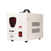


Contact-type voltage stabilizers widely used in households, factories, laboratories and other settings as key equipment to ensure stable power supply. However, in practice, users often encounter output voltage instability, overheating, failure to start, abnormal noise, frequent tripping and so on. This article will combine specific cases and professional analysis, systematically combing the causes and solutions of these common problems, to help users effectively troubleshoot and ensure the stable operation of equipment.
1.Voltage of unstable output: large fluctuations or deviations from set values
(1) Core reasons
Input voltage fluctuation: If the input voltage exceeds the rated range of the voltage stabilizer (e.g. ±20%) or the grid voltage surges frequently (e.g. lightning strikes, high power equipment start and stop), the voltage the voltage stabilizer may not be able to react in a timely manner. For example, in a CT room at a hospital, due to lightning strike strike, the input voltage suddenly rose to 280V, exceeding the the voltage stabilizer's range, causing fluctuations in output voltage.
load variation Overload: When the load exceeds the rated capacity of the regulator, the regulator its regulating capability will fail. For example, a factory used a voltage regulator rated at 10kVA to drive a motor of 15 kW, causing output voltage fluctuation of + -± 15%.
Internal components aging: Carbon brush carbon brush capacitor leakage capacitor leakage winding short-circuit Component aging issues will directly reduce voltage stabilization accuracy. For example, in a certain laboratory voltage stabilizer, carbon brushes wear leads to an increase in contact resistance, resulting in an increase in output voltage fluctuation from ±1% to ±5%.
Circuit design defect: Feedback circuit parameter drift, control chip failure and other design problems may lead to output out of control. Due to the incorrect parameters of the feedback circuit components, the output voltage of a data center voltage stabilizer is always 30V higher than the normal voltage.
(II) Solutions
Input voltage management
Surge protectors (SPDS) are used to suppress transient overvoltage. For example, by installing SPDS, the provincial CDC reduced voltage fluctuation caused by lightning strikes from ±30% to ±5%.
For persistently low input voltage (e.g. rural power grids), a voltage stabilizer with a wide input range (e.g. ± 50%) is an option.
Load matching optimization
Strict adherence to the principle of voltage regulator rated power ≥ 1.5 load total power. For example, when driving a 2.2kW motor, a regulator with a capacity ≥ 3.3 kVA should be selected.
For inductive loads (such as air conditioners and compressors) that are frequently started and stopped, a larger allowance should be made. A hotel has equipped its central air air conditioning system a The voltage stabilizer that is 2.5 times the capacity of the load, successfully avoiding voltage drops caused by start shock.
Component maintenance and replacement
Wash the contact surface between the brush and coil regularly and replace the carbon brush if necessary. A pharmaceutical company replaced the carbon carbon brushes six months, reducing the failure rate the the voltage stabilizer by 70%.
Test the capacitance and leakage current capacitors and replace the bulging or leaking capacitors. An electronics factory replaced aging capacitors in batches, reducing the output voltage ripple from 500mV to 50 mV.
Circuit calibration and upgrading
Contact manufacturer to recalibrate feedback circuit parameters. The output voltage accuracy of a bank data center was restored from ±2% to ±0.5% by calibration.
Upgrade control chip or replace circuit board. The output voltage drift problem is solved by replacing the main control board in a communication base station.
2. Overheating the voltage stabilizer: Unusual increase in housing temperature
(1) Core reasons
Overload operation: When load power exceeds the rated capacity, the voltage regulator will continue to operate under high load. For example, a plant used a a 5kVA voltage stabilizer to drive an 8kW device to a surface temperature of 85°C (rated limit is 65°C).
Cooling system failure: fan shutdown, blocked heat sink, blocked ventilation port, will greatly reduce cooling efficiency. The internal temperature of a laboratory voltage stabilizer rose from 40°C to 90°C in just 10 minutes because the fan bearing were jammed.
Ambient temperature is too high: In high temperature environment (such as machine room without air conditioning), the heat dissipation efficiency of regulator will be reduced. During the hot summer months, the output of a voltage regulator at an outdoor base station decreased by 20% as ambient temperatures reached 45 degrees Celsius.
(II) Solutions
Load control
Reduce load power immediately to prevent equipment damage. One hospital reduced some of its load from 80°C to 55°C on a the voltage stabilizer.
Choose a larger capacity voltage stabilizer. When a factory replaced the 5kVA equipment with a 10kVA model, the temperature stabilized at 50°C when operating at full capacity.
Heat dissipation system maintenance
Clean the dust from the heat sink and keep the ventilation holes unobstructed. the heat dissipation efficiency of the regulator has been improved by 30% by regular cleaning in a data center.
Replace faulty fans or upgrade cooling designs. A communication base station reduced the temperature of the equipment by 15°C by installing auxiliary fans.
Optimizing the environment
Install air conditioners or mandatory ventilation equipment in hot environments. An outdoor base station lowered the temperature by 20°C by installing umbrellas and ventilation fans.
Choose an oil-soaked or fully sealed regulator. a certain metallurgical enterprise can still operate steadily at 50 ℃ after using oil immersion equipment.
iii. The voltage stabilizer fails to start: indicator light not on or output not available
(1) Core reasons
Power failure: Common causes include unconnected input power, blown fuse or loose plug. A household voltage stabilizer cannot be started due to poor socket contact. After replacing the socket, the problem was solved.
Internal component damage: Transformer winding short circuit, control board failure or relay adhesion will lead directly to startup failure. The voltage stabilizer of a factory was restored to normal after replacement due to short circuit of transformer winding.
Protection circuit Trigger: Overvoltage, overvoltage, or overtemperature protection action will lock the device. A The voltage stabilizer in a laboratory triggered an undervoltage protection because the input voltage was too low. After adjusting the input voltage, the reboot was successfully completed.
(II) Solutions
Power supply check
Make sure the input power supply is normal (measure voltage with a multimeter). A hospital inspection found that the input voltage was 0V, because the distribution box tripped.
Replace fuse (same specification and model should be selected). A household voltage stabilizer could not be activated because of a fuse. Replaced and restored.
Component inspection and replacement
Test the resistance of the transformer winding to determine if there is a short circuit. Measurement at a factory found that the winding resistance was 0 omega. The transformer was replaced after a short circuit was identified.
Check the indicator lights and signal outputs on the control board and replace the faulty control board card. By replacing the control board, one data center solved the problem that the equipment could not start.
Protection circuit reset
Press the reset button (if any) or disconnect the power, then restart. The overtemperature protection lock is unlocked by reset operation a communication base station.
Check for reasons to protect the trigger (such as input voltage anomalies) and restart after troubleshooting. A laboratory restored the normal start of the equipment by adjusting the input voltage.
IV. Abnormal Noises: buzzing or ticking
(1) Core reasons
Loose mechanical parts: Loose transformer cores, vibrations from carbon brush racks or fan bearings can cause noise. The voltage stabilizer in one factory humming sound continuously during operation as the screws holding the iron core loosened.
Poor electrical contact: carbon brushes have poor contact with coils, relay contacts oxidation or loose terminal blocks can cause electrical sparks and noise. A household voltage stabilizer clicked as it ran due to the wear and tear of carbon brushes.
Load Characteristics Impact: Frequent start and stop of an inductive loads,such as an electric motor, may cause internal vibration of the voltage stabilizer. The voltage stabilizer of a machine tool produces noise due to the resonance of internal components caused by the impact of motor startup.
(II) Solutions
... the fastening of mechanical components.
Tighten the screws holding the transformer core to eliminate vibration. A factory tightened screws to reduce noise from 70 decibels to 40 decibels.
Replace worn fan bearings or install shock absorbers. A data center reduced noise by 15 decibels by replacing fans.
contact optimization
Clean contact surface between carbon brush and coil. Replace the carbon brush if necessary. A household voltage stabilizer eliminated ticking by replacing carbon brushes.
Grind relay contacts or replace the contactor. The noise caused by oxidation of contactor is solved by replacing the contactor in a factory.
Load Management
Avoid starting and stopping loads frequently, or choosing a soft-start device. By installing a soft starter, a machine tool can reduce the impact of starting shock on the voltage the voltage stabilizer.
Configure filters for inductive loads to inhibit sudden changes in current. By installing a filter, a communication base station can reduce the interference of load to the voltage stabilizer.
V. Frequent tripping: protection indicator lights flashing.
(1) Core reasons
Overload or short circuit: protection is triggered when load power exceeds rated capacity or when a short circuit occurs on the line. the voltage stabilizer are frequently tripped in a factory with a load of 12kW (rated 10kVA).
Error operation of protection circuit: component aging or parameter drift may lead to error protection. The voltage stabilizer a data center triggers overvoltage protection when the input voltage was normal due to the malfunction of the voltage detection module.
Grounding Fault: Bad contact or disconnection of the ground wire will cause the grounding potential to drift, triggering protection. The output voltage of a laboratory voltage stabilizer fluctuates due to the disconnection of the ground wire and triggers protection.
(II) Solutions
Load and Short circuit Troubleshooting
Reduce load power to rated range. A factory distributes load to prevent the voltage stabilizer from tripping.
Measure the insulation resistance of the circuit using multimeter to eliminate short circuit fault. Upon inspection, a short circuit was found in a household. After replacement, the problem was solved.
Calibration protection circuit
Contact the manufacturer to recalibrate protection parameters (e.g. overvoltage and undervoltage thresholds). A data center calibrated the overvoltage protection threshold from 250V to 245 V, avoiding misoperation.
Replacement of fault detection module. The problem of protection false triggering was solved by replacing voltage detection module in a laboratory.
Grounding system inspection
Make sure the ground wire is strong and the grounding resistance does not exceed 4 omega. A factory reduced grounding resistance from 10 to 2 omega by tightening ground wire screws.
Check the continuity of the ground wire and troubleshoot the disconnection. One family tested positive and found the ground wire was disconnected. After reconnection, the voltage stabilizer returned to normal.
Conclusion:
The steady operation of contact-type voltage stabilizers depends on scientific selection, specification installation and regular maintenance. Users should select equipment of appropriate capacity based on load characteristics, install it in strict compliance with installation specifications (e.g. grounding requirements), and establish regular maintenance systems (e.g. cleaning dust and checking components every six months). When a fault occurs, it can be investigated step by step according to the principles of ``first supply, then load; first mechanical, then electrical; first simple, then complex ''. For complex failures (such as the control board damage), it is recommended to contact a professional repairman or manufacturer for technical support to avoid secondary damage due to improper operation. Through system management, the reliability and service life of voltage stabilizers can be significantly improved, providing stable power supply for key equipment.